
How Does a Sewage Pumping Station Work? A Technical Breakdown
Filed under: Water and Wastewater Treatment

Sewage pumping stations are the unsung infrastructure holding municipal wastewater systems together. If you’re specifying, building, or maintaining one, you already know the stakes: a failed pump station doesn’t just inconvenience residents. It backs up sewage, triggers regulatory headaches, and puts the project team in the headlines for the wrong reasons.
This breakdown covers what a sewage pumping station actually does, how the major components work together, and what fabrication decisions matter most before a single weld is made.
What Is a Sewage Pumping Station?
A sewage pumping station (also called a sewage lift station) is a facility that transports wastewater upwards, from low-lying areas to a higher elevation, so it can continue flowing through the collection network toward a wastewater treatment plant.
Gravity handles most of a collection system, but two terrain conditions make continuous gravity flow either impractical or impossible:
- Flat, low-lying areas: Not enough natural slope to maintain the minimum pipe velocity needed to keep solids moving
- Hilly terrain: Maintaining grade would require burying pipes so deep that excavation costs become prohibitive
In both cases, a pumping station lifts wastewater back up near the surface, where gravity can take over again.
Where Does It Fit in a Wastewater Network?
A pumping station sits at a low point in the collection system, receiving gravity-fed flow from upstream sewer lines. From there, it pumps wastewater through a pressurized forcemain to either a treatment facility or a higher point in the collection system, where gravity takes over again.
The station’s position in the network determines its design parameters:
- Expected peak flow rates
- The number and capacity of pump sets
- Forcemain diameter
- The pressure the piping system needs to handle
In a large-scale development such as a new subdivision or mixed-use community, a single pumping station may serve tens of thousands of residents for decades. That scale drives tight specifications on materials, fabrication tolerances, and piping layout.
How Does a Pumping Station Work?
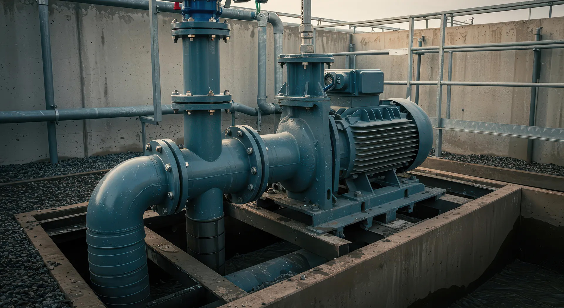
Wastewater arrives at the pump station through gravity sewer lines and collects in an underground chamber called the wet well. Level sensors in the wet well continuously monitor the incoming flow.
When the sewage level reaches a set trigger point, the control system activates one or more submersible pump stations. The pumps draw sewage from the wet well and push it through a discharge header, then through check and isolation valves, and out to the forcemain. The forcemain carries the pressurized flow to its discharge point.
Once the wet well drops to a lower set point, the pumps shut off and the cycle repeats.
Most modern stations run multiple pumps in rotation to distribute wear evenly and provide redundancy in the event of a pump failure.
The pump cycles continuously, 24/7. The mechanical and piping systems have no scheduled downtime unless maintenance is planned. That’s why material selection, fabrication quality, and valve layout all have long-term maintenance implications from day one of design.
Key Components of a Sewage Pumping Station
A pumping station is a system of interdependent components. A failure or specification error in any one of them affects the others. Here’s how each major component functions.

The Wet Well
The wet well is the below-grade concrete chamber that receives incoming sewage from the collection system. It serves as a buffer, absorbing flow variation between pump cycles.
Wet well sizing is calculated based on peak design flow and pump cycling frequency. Too small, and pumps short-cycle, burning out motors prematurely. Too large, and wastewater sits too long, generating hydrogen sulfide gas and creating corrosion and odour problems.
The wet well also houses the submersible pump sets on guide rails, which allow pumps to be lifted out for service without dewatering the structure. Level sensors (float switches or pressure transducers) feed data to the control panel that governs when pumps start and stop.
Pump Sets
Pump sets consist of the submersible sewage pumps, discharge elbows, guide rails, and lifting chains or cables. Each pump connects to the station’s discharge piping via a mating discharge elbow bolted to the wet well floor.
Pump selection is driven by the design flow rate and total dynamic head (TDH), which accounts for elevation change plus friction losses through the forcemain and fittings. Undersized pumps can’t achieve the required flow; oversized pumps waste energy and may not provide adequate velocity in the forcemain to keep solids in suspension.
Most stations are designed with at least two pump sets so that one can operate while the other undergoes maintenance. For larger stations serving significant populations, three or four pump sets are common, with staggered operation.
The Valve Chamber
The valve chamber is a separate structure, adjacent to or above the wet well, that houses the isolation and check valves on each pump’s discharge line. Separating valve access from the wet well itself is a critical safety and operational design decision. Maintenance staff can isolate, inspect, and service valves without entering a confined space or working directly over sewage.
Each pump discharge line typically includes a check valve (to prevent backflow when the pump shuts off) and an isolation valve (to take a pump offline without affecting the others). The piping layout in the valve chamber also includes pressure gauges, air release valves, and, in some designs, flow meters.
The valve chamber piping sees repeated pressure cycling as pumps start and stop, plus the full operating pressure of the forcemain. That cycling, combined with the corrosive atmosphere, sets the baseline for material and fabrication requirements.
The Forcemain Gallery
The forcemain gallery is the section of piping that conveys pressurized sewage from the pump station discharge out to the forcemain network. It connects the valve chamber’s outlet headers to the buried forcemain pipe and often includes the final pipe size transitions and connection flanges.
Forcemain sizing is determined by velocity requirements: fast enough to keep solids moving (typically a minimum of 0.6 m/s), but not so fast that pipe wear and pressure surge become a problem. Where multiple pump combinations are possible, the designer needs to verify minimum velocity is maintained under all operating scenarios.
The gallery piping also handles water hammer loads when pumps cycle. Check valves, properly sized air release valves, and surge analysis all factor into whether those loads stay within the pipe and fitting system’s pressure rating.
How Pump Station Piping Is Specified and Fabricated
Piping inside a pump station valve chamber or forcemain gallery usually isn’t off-the-shelf work. While standard valves, fittings, and pipe materials may be used, the spools are often custom-fabricated to fit large diameters, tight spaces, wall penetrations, supports, and as-built civil dimensions. If spools are measured or fabricated incorrectly, they may not line up after concrete is poured, resulting in costly rework or delays.
Material Selection
Stainless steel, typically 316, is the standard choice for wet well discharge piping and valve chamber piping in sewage applications. Its corrosion resistance withstands hydrogen sulfide gas, wet/dry cycling, and mildly acidic conditions in raw sewage.
Carbon steel is used in less aggressive service, but in valve chambers where atmosphere, moisture, and H2S are present, the long-term maintenance costs of carbon steel generally outweigh any upfront savings. Where carbon steel is used, interior lining (epoxy or cement mortar) is common.
Schedule selection depends on operating pressure, water hammer loads, and the specific allowances in the applicable codes (AWWA, CSA, ASTM).
Pipe Sizing
Sizing in pump station piping isn’t just about flow capacity. The designer and fabricator both need to account for:
- Velocity minimums and maximums at each pump combination scenario
- Pipe reducer placement and whether concentric or eccentric reducers are required (eccentric reducers are standard at pump discharge to avoid air trapping)
- Flange placement to allow valve removal without cutting pipe
- Clearances within the structure for insulation, supports, and personnel access
Fabrication drawings need to reflect as-built civil dimensions, not just design intent. Any discrepancy between the structural opening dimensions and the fabricated spool lengths creates field-fit problems that are expensive to resolve after the fact.
Flanging
Flanges are the primary connection method in pump station piping because they allow sections to be disassembled for maintenance without cutting. In sewage service, that means every pump discharge line and valve assembly needs properly spaced flanges at access points.
Flange face standards (flat face vs. raised face), bolt pattern, and pressure class must match those of adjacent equipment. Submersible pumps often use ANSI/AWWA flanges, while valves may use ANSI 150 or 125 lb flat face, depending on the manufacturer. Mixing these without proper attention to gasket selection and bolt torque is a leak waiting to happen.
High-quality shop fabrication means flanges are square, face finish is correct for the gasket type, and bolt holes are aligned before anything ships to the site.
NDT Requirements
Municipal and institutional sewage pumping stations typically require some level of nondestructive testing on welded joints, depending on the jurisdiction, the engineer of record specifications, and applicable codes.
Common NDT methods for pump station piping include:
- Visual inspection (VT): Required on all welds as a baseline
- Dye penetrant testing (PT): Used on stainless steel welds to detect surface-breaking defects
- Radiographic testing (RT): Specified for higher-pressure or critical joints where full weld integrity is required
- Ultrasonic testing (UT): An alternative to RT where radiography isn’t practical
Fabricators need the right certifications, qualified procedures, inspection planning, and documentation in place before work begins. When NDT requirements are treated as an afterthought, shops can run into missing records, delayed inspections, rejected welds, and costly rework.
Shops that build NDT into their standard process handle this without scheduling impacts.
Case Study: Lakeview Village Sewage Pumping Station
Our team fabricated 316 stainless steel schedule 40 piping for the valve chamber and forcemain gallery at the Lakeview Village Sewage Pumping Station in the Region of Peel, Ontario. The scope covered four 16″ wet well discharge pumps and two 20″ forcemains, with pipe diameters ranging from 3″ to 24″.
The project included custom-fabricated 45° wye laterals, Y-shaped fittings in which two pipe branches meet at a single outlet at 45 °. On a 20″ forcemain, these aren’t stock items. They require precise layout, custom cutting, and full-penetration welds sized to handle the cycling pressure loads of an active pump station.
Looking for a Fabricator for Your Pump Station Project?
Sewage pumping station piping requires fabricators who understand municipal specifications, can work with tight dimensional tolerances, and have the stainless steel welding and process documentation to meet engineer requirements.
Maplevale Fabrications has over 35 years of experience fabricating pipe spools, fittings, and custom components for wastewater infrastructure across Ontario. Our shop handles pipe from 2″ to 108″ in diameter, with capabilities for 316 stainless steel and carbon steel, flanged assemblies, custom wye laterals, and NDT-ready weld procedures.
For GCs and project managers running tight schedules, our Revit MEP-based drafting process catches dimensional conflicts before fabrication starts, reducing field rework. For purchasing managers and estimators, we deliver clear quotes that reflect your drawings and specs, not generic line items that shift at invoicing.
If you have a pump station project in the pipeline, contact us to discuss your scope and timeline.